Rover MEMS 1.6 diagnostic protocol
Published: 2014-04-21
See also the Google discussion group.
Updates
2015-10-27: Converted the data frame offsets to hex and added a few more fields.
2015-06-12: I learned that the ECU's 32-byte response to the command 7D is also a frame of diagnostic data, and it contains some lambda sensor voltage and fuel trim information. I've added a new table toward the end of this article with a start to the description of this data structure. I also noted the idle error, ignition advance, and coil time fields in the data frame for command 80.
Overview
Earlier versions of Rover MEMS (Modular Engine Management System) use a round three-pin diagnostic socket and a proprietary software protocol known as ROSCO (ROver Service COmmunications). With an oscilloscope, I was able to determine the signalling characteristics and baud rate, and a logic analyzer revealed some basic information about the protocol. Here in North America, early versions of this system are very uncommon. I only have access to a couple MEMS 1.6 SPi units, so I don't know how much of my research applies to other configurations. The information collected in this article may be helpful for anyone working to reverse engineer the diagnostic protocol(s) used by other variants of the system, and I hope that others publish their findings as well.
Software
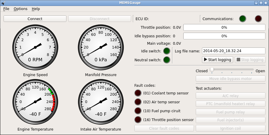
I've written some free, open-source software that can display diagnostic information and test actuators on MEMS 1.6. It's written in two parts, a library and a front-end graphical interface. To use it, you'll need to build a cable to connect to the car (see "Building a cable", below.) Both Linux and Windows versions are available to download:
Building a cable
To build a cable that will connect to the ECU's diagnostic port, you will need three things:
-
A 5V (TTL level) USB to serial converter. I strongly recommend the FTDI TTL-232R-5V. Note that it's important to have a 5V converter -- a normal RS-232 port will not work, and neither will a converter that uses regular RS-232 voltage levels. The FTDI cable (or an equivalent, such as the GearMo 5V cable) is available from different retailers:
If you're in the UK/Europe, you may want to check your local Amazon site for one of these. Remember that it is important to get one that uses 0V-5V voltage levels.
-
A TE Connectivity type 172201 connector, which will mate to the connector on the car's diagnostic port. The shell for this connector is available from different retailers, although stock quantities may vary:
-
Three pins for the connector shell. The pins are also manufactured by TE Connectivity, part number 170280 for strips of 50. I've been told that they're also available singly, part number 170293.
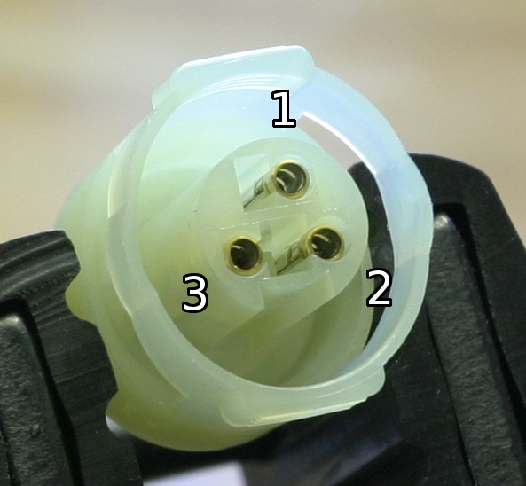
Once you have the above components, solder leads onto the pins, insert them into the connector shell, and solder the FTDI cable wires to the pin leads according to the following table. For the pin numbering on the 172201 connector, look at the face of the connector with the key (notch) on the bottom. The first pin (C549-1) will be on the top, and the numbering continues clockwise. (If you're looking at the mating connector in the car, the numbering goes counter-clockwise.)
When looking for the diagnostic connector on the vehicle, note that cars with a security/immobilizer module (such as the Lucas 5AS) will often have a second connector of the same type. On the Mini SPi, the engine ECU connector is beige, while the security module connector is green. Make sure you're connecting to the right one.
Table 0: Pin assignment for USB PC interface cable
| Pin number | FTDI wire color | Pin assignment | Wire color on mating connector in car |
|---|---|---|---|
| C549-1 | Black | Signal ground | Pink w/ black |
| C549-2 | Yellow | Rx (car ECU to PC) | White w/ yellow |
| C549-3 | Orange | Tx (PC to car ECU) | Black w/ green |
Protocol
The ECU's diagnostic port uses a serial protocol, with 8 data bits, no parity, and 1 stop bit, running at 9600 bps.
When a diagnotic tool (or a PC running diagnostic software) is first connected to the ECU, it must send an initialization sequence to enable further communication. I haven't looked inside the SPi MEMS firmware and I've only run experiments with a single car, so I can't provide any further insight on the meaning of this sequence. I'd certainly like to hear from anyone who has more information. Note that the first byte returned by the ECU appears to always be an echo of the command byte.
Table 1: Initialization sequence
| Sent by tool | Response from ECU (MNE101170) | Response from ECU (MNE101070) |
|---|---|---|
| CA | CA | CA |
| 75 | 75 | 75 |
| D0 | D0 99 00 03 03 | D0 99 00 02 03 |
Once the initialization sequence is complete, any of several single-byte commands may be sent to the ECU. They are described in Table 3.
Some of the commands appear to increment or decrement settings that have a predefined range. The settings that I've found are described in Table 2.
Table 2: Software counters/settings used in the firmware on MNE101170. All values in hex.
| Setting | Default value | Minimum | Maximum | Decremented by command(s) | Incremented by command(s) |
|---|---|---|---|---|---|
| Fuel trim | 8A | 00 | FE | 7A and 7C | 79 and 7B |
| Idle decay | 23 | 0A | 3C | 8A | 89 |
| Idle speed | 80 | 78 | 88 | 92 | 91 |
| Ignition advance offset | 80 | 74 | 8C | 94 | 93 |
Although some of the actuators have pairs of on/off commands to drive them, I've found that the system fitted to the Mini SPi will actually turn off the AC relay, PTC relay, and fuel pump relay automatically after a short time (i.e. without requiring the 'off' command). The 'off' command is acknowledged by the ECU, but apparently has no effect.
Table 3: Protocol command bytes (values in hex)
| Command byte (sent to ECU) | Description | Response from ECU (MNE101170) |
|---|---|---|
| 01 | Open fuel pump relay (stop fuel pump) | 01 00 |
| 02 | Open PTC relay (inlet manifold heater) | 02 00 |
| 03 | Open air conditioning relay | 03 00 |
| 08 | Close purge valve? | 08 00 |
| 09 | Open O2 heater relay? | 09 00 |
| 11 | Close fuel pump relay (run fuel pump) | 11 00 |
| 12 | Close PTC relay (inlet manifold heater) | 12 00 |
| 13 | Close air conditioning relay | 13 00 |
| 18 | Open purge valve? | 18 00 |
| 19 | Close O2 heater relay? | 19 00 |
| 1D | Close Fan 1 relay? Together with command 1E, I found through protocol analysis that this has something to do with testing an electric fan, but my ECUs didn't respond beyond the echo byte. | 1D |
| 1E | Close Fan 2 relay? | 1E |
| 65 | ? | 65 00 |
| 6D | ? | 6D 00 |
| 79 | Increments fuel trim setting and returns the current value. | 79 xx, where the second byte is the counter value |
| 7A | Decrements fuel trim setting and returns the current value. | 7A xx, where the second byte is the counter value |
| 7B | Increments fuel trim setting and returns the current value. | 7B xx, where the second byte is the counter value |
| 7C | Decrements fuel trim setting and returns the current value. | 7C xx, where the second byte is the counter value |
| 7D | Request data frame | 7D, followed by 32-byte data frame; see Table 4 |
| 7E | ? | 7E 08 |
| 7F | ? | 7F 05 |
| 80 | Request data frame | 80, followed by 28-byte data frame; see Table 5 |
| 82 | ? | 82 09 9E 1D 00 00 60 05 FF FF |
| 89 | Increments idle decay setting and returns the current value | 89 xx, where the second byte is the counter value |
| 8A | Decrements idle decay setting and returns the current value | 8A xx, where the second byte is the counter value |
| 91 | Increments idle speed setting and returns the current value | 91 xx, where the second byte is the counter value |
| 92 | Decrements idle speed setting and returns the current value | 92 xx, where the second byte is the counter value |
| 93 | Increments ignition advance offset and returns the current value | 93 xx, where the second byte is the counter value |
| 94 | Decrements ignition advance offset and returns the current value | 94 xx, where the second byte is the counter value |
| CB | ? | CB 00 |
| CC | Clear fault codes | CC 00 |
| CD | ? | CD 01 |
| D0 | ? | D0 99 00 03 03 |
| D1 | ? | D1 41 42 4E 4D 50 30 30 33 99 00 03 03 41 42 4E 4D 50 30 30 33 99 00 03 03 41 42 4E 4D 50 30 30 33 99 00 03 03 |
| D2 | ? | D2, followed by 02 01, 00 01, or 01 01 |
| D3 | ? | D3, followed by 02 01, 00 02, or 01 01 |
| E7 | ? | E7 02 |
| E8 | ? | E8 05 26 01 00 01 |
| ED | ? | ED 00 |
| EE | ? | EE 00 |
| EF | Actuate fuel injectors? (MPi?) | EF 03 |
| F0 | ? | F0 50 |
| F3 | ? | F3 00 |
| F4 | NOP / heartbeat? Sent continuously by handheld diagnostic tools to verify serial link. | F4 00 |
| F5 | ? | F5 00 |
| F6 | Unknown. Disconnect or sleep command? During a bench test, the Mini SPi ECU changed its behavior after being commanded with F6; it would only echo single bytes that it received, but nothing else. For example, sending 80 would cause it to echo 80 but no data frame followed. Re-sending the init sequence of CA, 75, and D0 restored normal behavior. | F6 00 |
| F7 | Actuate fuel injector (SPi?) | F7 03 |
| F8 | Fire ignition coil | F8 02 |
| FB | Request current IAC position | FB xx, where the second byte represents the IAC position |
| FC | ? | FC 00 |
| FD | Open IAC by one step and report current position | FD xx, where the second byte represents the IAC position |
| FE | Close IAC by one step and report current position | FE xx, where the second byte represents the IAC position |
| FF | Request current IAC position? |
The tables below describe the known fields in the data frames that are sent by the ECU in response to commands 0x7D and 0x80, respectively. Multi-byte fields are sent in big-endian format.
Table 4: Data frame (Command 0x7D)
| Byte position | Field |
|---|---|
| 0x00 | Size of data frame, including this byte |
| 0x01 | Unknown |
| 0x02 | Throttle angle? |
| 0x03 | Unknown |
| 0x04 | Sometimes documented to be air/fuel ratio, but often observed to never change from 0xFF |
| 0x05 | Unknown |
| 0x06 | Lambda sensor voltage, 0.5mv per LSB |
| 0x07 | Lambda sensor frequency? |
| 0x08 | Lambda sensor duty cycle? |
| 0x09 | Lambda sensor status? 0x01 for good, any other value for no good |
| 0x0A | Loop indicator, 0 for open loop and nonzero for closed loop |
| 0x0B | Long term trim? |
| 0x0C | Short term trim, 1% per LSB |
| 0x0D | Carbon canister purge valve duty cycle? |
| 0x0E | Unknown |
| 0x0F | Idle base position |
| 0x10 | Unknown |
| 0x11 | Unknown |
| 0x12 | Unknown |
| 0x13 | Unknown |
| 0x14 | Idle error? |
| 0x15 | Unknown |
| 0x16 | Unknown |
| 0x17 | Unknown |
| 0x18 | Unknown |
| 0x19 | Unknown |
| 0x1A | Unknown |
| 0x1B | Unknown |
| 0x1C | Unknown |
| 0x1D | Unknown |
| 0x1E | Unknown |
| 0x1F | Unknown |
Table 5: Data frame (Command 0x80)
| Byte position | Field |
|---|---|
| 0x00 | Size of data frame, including this byte. This should be 0x1C (28 bytes) for the frame described here. |
| 0x01-2 | Engine speed in RPM (16 bits) |
| 0x03 | Coolant temperature in degrees C with +55 offset and 8-bit wrap |
| 0x04 | Computed ambient temperature in degrees C with +55 offset and 8-bit wrap |
| 0x05 | Intake air temperature in degrees C with +55 offset and 8-bit wrap |
| 0x06 | Fuel temperature in degrees C with +55 offset and 8-bit wrap. This is not supported on the Mini SPi, and always appears as 0xFF. |
| 0x07 | MAP sensor value in kilopascals |
| 0x08 | Battery voltage, 0.1V per LSB (e.g. 0x7B == 12.3V) |
| 0x09 | Throttle pot voltage, 0.02V per LSB. WOT should probably be close to 0xFA or 5.0V. |
| 0x0A | Idle switch. Bit 4 will be set if the throttle is closed, and it will be clear otherwise. |
| 0x0B | Unknown. Probably a bitfield. Observed as 0x24 with engine off, and 0x20 with engine running. A single sample during a fifteen minute test drive showed a value of 0x30. |
| 0x0C | Park/neutral switch. Zero is closed, nonzero is open. |
| 0x0D | Fault codes. On the Mini SPi, only two bits in this location are checked: |
| Bit 0: Coolant temp sensor fault (Code 1) | |
| Bit 1: Inlet air temp sensor fault (Code 2) | |
| 0x0E | Fault codes. On the Mini SPi, only two bits in this location are checked: |
| Bit 1: Fuel pump circuit fault (Code 10) | |
| Bit 7: Throttle pot circuit fault (Code 16) | |
| 0x0F | Unknown |
| 0x10 | Unknown |
| 0x11 | Unknown |
| 0x12 | Idle air control motor position. On the Mini SPi's A-series engine, 0 is closed, and 180 is wide open. |
| 0x13-14 | Idle speed deviation (16 bits) |
| 0x15 | Unknown |
| 0x16 | Ignition advance, 0.5 degrees per LSB with range of -24 deg (0x00) to 103.5 deg (0xFF) |
| 0x17-18 | Coil time, 0.002 milliseconds per LSB (16 bits) |
| 0x19 | Unknown |
| 0x1A | Unknown |
| 0x1B | Unknown |