14CUX diagnostics
2014-02-10
The Lucas 14CUX is an electronic engine management system designed to control fuel injection on the Rover V8 engine. It was used primarily in Land Rover products from its introduction in 1990 until 1995, and also by low-volume sports car manufacturers (TVR, Morgan, Marcos, Ginetta) until the engine ceased production around 2005. More information about the high-level design and applications of the 14CUX can be found in its Wikipedia article.
The Rover V8 has a tuning potential that made it popular with specialist sports car builders, and it exists in a variety of configurations from 3.5L to 5.0L displacement and beyond. The fuel maps stored in the 14CUX each represent a two-dimensional array of fueling values, indexed by engine speed and engine load. There are at least two reasons that a person may want to design a custom fuel map:
- The fuel maps are usually specific to a particular engine displacement; a 3.5L fuel map will not work well with a 5.0L engine. Appropriate fuel maps could be used to allow retrofitting the 14CUX system to later Rover V8 configurations -- these may include the 4.0L and 4.6L units, which were sold in the United States with a different engine management system after the 14CUX had been discontinued.
- Engines being tuned for motorsport have different performance requirements than those that were designed for road use. Fuel maps can be modified to increase power at the expense of fuel economy.
The purpose of this project is to explore and document the internal function of the 14CUX. Exploration of the 14CUX firmware has also uncovered a software protocol that can be used to communicate with the ECU and retrieve diagnostic information over its serial link.
Hardware
In Land Rover vehicles, the ECU will have a Land Rover part number starting with either "PRC" (for earlier units) or "AMR" (for later units).
The microprocessor used by the 14CUX is a Motorola 6803U4, which is an uncommon variation of the 6803. The "U4" has three built-in timers as opposed to the standard 6803's single timer; this is important, as the fuel injectors are batch-fired an entire bank at a time, and each of the left and right banks requires its own timing.
The code and data is stored in a 27256 PROM, which seems to be soldered in place in earlier (PRC) units and socketed in later units (PRC and AMR). Only half of the 32KB space is used, so the 16KB of code and data is duplicated in the upper half.
Memory map
The 64KB address space is not fully utilized and some devices are mapped into memory in multiple locations. For example, the 16KB ROM contents appears in $C000-$FFFF, and again in $8000-$BFFF. The four ADC registers repeat from $4000 to $7FFF. If an empty memory location is read, the low byte of the address is returned as the data. (Thus, if displaying a block of memory read from an empty location, it will appear as an incrementing count.)
The low area of the ROM ($C000-$C83F) contains the fuel maps and other data. The area from $C840 to $FFFF contains code, jump tables, and a few fixed data tables. Code stops around $FA50, and is followed by an unprogrammed section. The unprogrammed area of the ROM continues until near the end, where a vector table is located.
| Address | Device | Description |
|---|---|---|
| $0000-$0020 | MPU | 6803U4 internal register block |
| $0040-$00FF | MPU | 6803U4 RAM; first 32 bytes ($40 to $5F) are battery-backed and used to hold fault codes |
| $2000-$207F | PAL? | External RAM (repeats from $2000 to $3FFF) |
| $4004-$4007 | PAL | $4000 |
| $6000-$6004 | ADC | A/D converter registers (repeats from $6000 to $7FFF) |
| $C000-$FFFF | ROM | The contents of the ROM appear both here and in $8000-$BFFF |
Notable offsets
| Address | Contents |
|---|---|
| $C000 | ROM image (16KB) |
| $0049-$004E | Fault codes (see fault bits table, below) |
| $0055/56 | Main battery voltage (16 bits). This is used as input to the fueling value since it affects the opening time of the injectors. |
| $0059/5A | Mass airflow sensor voltage (16 bits). The A/D converter does a 10-bit reading of the MAF voltage and stores it as a 16-bit value in these locations. |
| $005B | Fuel map row index. This is calculated mainly from engine load (determined by air flow) with some scaling from engine speed. The value will be from 0x00 to 0x70. The upper nibble can have eight different values (0 thru 7). This will indicate the row in the 16-column by 8-row fuel map. |
| $005C | Fuel map column index. The firmware looks up one of sixteen engine RPM brackets and stores the corresponding number (from 0x0 thru 0xF) in the upper nibble of this memory location. |
| $005F/60 | Throttle position (16 bits). The 10-bit throttle pot value is stored here. The pot is spring-loaded to its minimum position, but is mounted with the wiper just off the minimum setting. If the pot is removed from its mounting and allowed to read below a certain threshold, the firmware will detect a fault. |
| $00A4/A5 | The throttle pot reading is copied to this location before the throttle pot routine finishes. The next time the routine runs, the new reading (at $005F/60) is compared with this. If the new reading is greater than the old reading by a certain threshold, it means that the throttle is opening quickly. In this case, the fueling is immediately increased. This can be thought of as a software equivalent of the carburetor accelerator pump. |
| $006A | Coolant temperature. |
| $006D | Idle bypass motor position. On startup, this will read 0, which is fully open. Fully closed is 180. |
| $007A-$007B | Engine speed (instantaneous) (16 bits). This is the instantaneous engine ignition pulse width measured in 2-microsecond increments. This is the time between two consecutive ignition pulses from the ignition coil. To obtain RPM, divide 7,500,000 by this number. |
| $007C-$007D | Engine speed (filtered) (16 bits). This is a running average of the ignition pulse width, and is calculated by averaging three old values and one newly-measured value. The result is a value that changes more smoothly, though it does not precisely represent the most current measurement. Since this filtered speed lags the instantaneous value, it's possibly useful to indicate whether the engine is revving up or slowing down. |
| $007E-$007F | Engine speed (RPM) (16 bits). This is the actual engine RPM, which the firmware calculated by dividing 7,500,000 by the above pulse width. This calculation is bypassed when the engine speed goes above 1950 RPM. This was probably done because the microprocessor gets very busy at higher RPMs; the processor doesn't have a divide instruction, and it is computationally expensive to calculate the RPM without one. |
| $2000 | Transmission gear / neutral switch. With an automatic transmission, this will read zero in park and a full 8-bit count (0xFF) when in drive. Testing with a Defender 90 manual (NAS) showed that the value stayed at half count (0x7F hex), probably indicating a resistor on this ADC input to put the ECU in manual-gearbox mode. |
| $2003 | Road speed in kilometers per hour. |
| $2006 | Fuel temperature. This value will start about the same as the coolant for a completely cooled engine but will not drop as much as the engine warms since the fuel does not get nearly as hot as the coolant. |
| $202C | Currently selected fuel map. (This is always 5 on NAS Land Rover vehicles.) |
| $2041 | Checksum of the ROM. This must always be 0x01, or the code will register a fault. (When the ROM image was being finalized, a particular byte was modified to force the contents of the ROM to produce an 8-bit checksum value of 0x01.) |
Fault bits
Fault bits are packed into memory locations $0049 through $004E, as shown below. Shaded cells represent an extended set of fault codes. Update, 2013-12-24: There seems to be a contradiction between the Land Rover documentation and the firmware, with regard to the bank-specific fault codes. I've updated the table below with the correct data. Note that I'm now using the terms 'odd' (cylinders 1-3-5-7) and 'even' (cylinders 2-4-6-8) to differentiate the banks, as this is less ambiguous than "left/right" or "A/B".
| 7 | 6 | 5 | 4 | 3 | 2 | 1 | 0 | |
|---|---|---|---|---|---|---|---|---|
| $0049 | (21) Tune resistor out of range | (12) Airflow meter | (50) Misfire (odd) | (40) Misfire (even) | (spare) | (45) O2 sensor (odd) | (44) O2 sensor (even) | (29) ECU checksum error |
| $004A | (88) Purge valve leak | (19) Throttle pot low with MAF high | (18) Throttle pot high with MAF low | (17) Throttle pot | (14) Coolant temp sensor | (36) Injector (even) | (spare) | (34) Injector (odd) |
| $004B | (spare) | (28) Intake air leak | (spare) | (26) Mixture too lean | (spare) | |||
| $004C | (69) Neutral (gear selector) switch | (68) Road speed sensor | (spare) | (48) Idle valve stepper motor | (spare) | (23) Low fuel pressure | ||
| $004D | (spare) | (15) Fuel temperature sensor | (58) Ambiguous: low fuel pressor or intake air leak | (spare) | ||||
| $004E | (02) RAM contents unreliable (battery disconnected) | (03) Bad checksum on battery-backed RAM | (spare) |
Analog-to-digital converter
The analog-to-digital converter used by the 14CUX is a Hitachi HD46508. It is a 16-channel device that is capable of 8-bit conversions, 10-bit conversions, and comparator operations. The following table shows the assignment of channels:
| Channel | Parameter | Mode |
|---|---|---|
| 0 | Inertia switch | 8-bit |
| 1 | Heated screen sense | 8-bit |
| 2 | Airflow sensor | 10-bit |
| 3 | Throttle potentiometer | 10-bit |
| 4 | Coolant temperature thermistor | 8-bit |
| 5 | Gearbox neutral switch | 8-bit |
| 6 | Air conditioner load input | 8-bit |
| 7 | Road speed transducer | 8-bit |
| 8 | Main voltage | 8-bit |
| 9 | MAF sensor voltage (open-loop fuel maps only; not used for NAS Land Rovers) | 10-bit |
| 10 | Tune resistor (disabled in NAS Land Rovers) | 8-bit |
| 11 | Fuel temperature thermistor | 8-bit |
| 12 | Left O2 sensor | 8-bit |
| 13 | O2 sensor reference voltage | 8-bit |
| 14 | Diagnostic plug | 8-bit |
| 15 | Right O2 sensor | 8-bit |
Diagnostic port hardware interface
The serial port used by the 14CUX is nonstandard in a number of ways. For a PC to be able to communicate with it, the serial device on the PC must:
- invert its RxD line (with respect to normal RS232 signal polarity),
- be able to set a baud rate close to 7812.5 bps, and
- be able to receive a 12VDC signal without being damaged.
FTDI cable
You'll need to get a 5-volt FTDI USB-to-serial converter cable. Either the TTL-232R-5V-WE or the TTL-232R-5V works fine. (If you don't get the wire-ended ("-WE") cable, you'll need to cut the header connector off the end before attaching your own connector.) There are also other manufacturers that build cables using FTDI chips; I've successfully tested the similar GearMo cable. When using one of these cables, the software will set the correct baud rate automatically.
On the cables I've used, the Tx and Rx lines were orange and yellow, respectively. Check the documentation for your cable to be sure about the wiring.
Once you have the FTDI cable, it's a good idea to test it with a loopback: short the Tx and Rx lines, connect the USB end to a PC, and start a terminal emulator (such as PuTTY). Be sure to turn off local echo, and any characters you type should appear in the terminal.
Then, using the FT_PROG utility from FTDI, invert the polarity of the Rx line (click screenshot to enlarge) and program the new configuration to the device by selecting "Devices" -> "Program" or simply pressing Ctrl-P. After this, unplug and re-plug the USB end of the FTDI cable for the change to take effect.
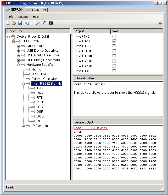
A loopback test in a terminal should no longer work once the Rx line is inverted.
Connector and wiring
The wiring harness in 14CUX-equipped vehicles already has a beige 5-pin connector on the serial port lines, but the shell for the mating connector is no longer available from most retailers. You will probably want to purchase a more common pair of mating connectors (such as a DB9), and use these instead. If you want to retain the original 5-pin connector on the vehicle's wiring harness, you can splice a different one in parallel.
The serial connector in the vehicle is usually located in the cabin. In the 1993 Range Rover (NAS), it is under the passenger seat; in the 1994 Defender (NAS), it is behind the passenger footwell kickpanel; in the 1994 Discovery (NAS), it is below the glovebox.
In most vehicles, the connector is mated to a grounding plug (i.e. the mating half of the connector with a pin installed to ground the ECU's Rx line.) You need to remove the grounding plug before connecting your FTDI cable.
Important: When you attach a connector to the wire end of the FTDI converter cable, you also need to add a resistor of about 390Ω between the FTDI's Rx line (usually yellow) and GND (usually black). This doesn't need to dissipate a lot of power, so a low-wattage resistor is fine. Cut back the FTDI cable's brown, green, and red wires, as they are not used. The connector wiring must allow the wires to mate up as shown in this table:
| FTDI cable signal | FTDI cable wire color | 14CUX harness signal | 14CUX harness wire color | 14CUX TTS connector pin |
|---|---|---|---|---|
| Tx | Orange | Rx | White w/ pink tracer | 1 |
| Rx | Yellow | Tx | White w/ light green tracer | 4 |
| GND | Black | GND | Black w/ gray tracer | 5 |
The TTS connector pin numbers in the table above are only important if you've managed to find a mating connector and want to wire it to match the existing TTS connector in the vehicle. The pins in the vehicle side are numbered like so:
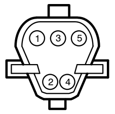
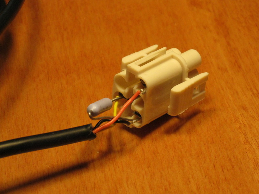
If you are using a TTS connector on the FTDI cable, the back of the connector shell will look like the photo below when it's wired correctly. Note the 400Ω resistor between pins 4 and 5 (click photo to enlarge):
That's it. The cable should now allow this software to communicate with the 14CUX.
Technical background
This section explains the reasons behind the unusual signalling characteristics of the 14CUX serial port. The output from the microprocessor (MPU) in the 14CUX's ECU looks like this:
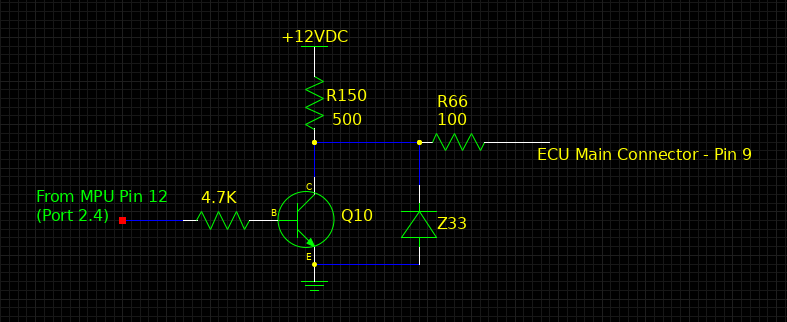
The Q10 transistor acts like a switch. When the signal from the MPU is high (5V), the switch is ON and the low side of R150 is shunted to ground, so Pin 9 is zero volts. When the MPU signal goes low, the switch is OFF and the low side of R150 is pulled up, so Pin 9 goes to 12V. This transistor circuit is designed to buffer and protect the MPU signal, but it also inverts and changes the voltage level. This is why the FTDI USB device must have its RxD signal inverted (to match the 14CUX's inverted TxD.) However, because the FTDI converter is a 5V device, the 12V signal from the ECU must be attenuated with an external resistor to prevent damage. I've found that the 5V signal from the FTDI converter is sufficient to drive the RxD line in the 14CUX.
The resistor needs to be about 400Ω and soldered between the ECU's output signal and ground. The total resistance will be 400Ω + 100Ω + 500Ω (1000Ω total). The voltage across the 400Ω resistor will be about 4.8V (400/1000 x 12V).
The serial port pins are brought out from the harness via the "Data Link Connector", which is C245 in the Land Rover service documentation. Its grounding plug is connector C244.
Serial software protocol
The protocol works as follows: the client sends a series of bytes to the 14CUX, which together specify the memory location to read or write and the number of bytes to read (if reading). When reading, a total of three bytes are sent before the 14CUX begins responding with the requested data. When writing, a total of four bytes are sent; the first three set the address (as with the "read" command) and the fourth is the value that will be written to the specified location.
With one exception, each byte sent to the 14CUX will be echoed back and the client should wait to receive each echo before sending the next byte. The single exception to this is the final byte of the "read" command -- instead of its echo, the 14CUX will immediately begin sending the requested data.
After a client has started sending a command, it is important that the remainder of the command be sent quickly: to avoid the possibility of waiting indefinitely for a partially-completed command, the 14CUX starts a timer when the first byte is received and can time-out if the client waits too long to finish.
The amount of time required for the 14CUX to send a character over the serial port may change depending on its current state; for example, read requests may be serviced slightly faster before the engine has been started due to the reduced load on the processor.
Command byte sequence and structure
The first command byte (call it Command Byte A) contains three fields: (a) a fixed identifier of 0, (b) the quantity of bytes to read (if applicable) and (c) the top two bits of the address that will be read/written. If performing a write command, the Quantity field is ignored. This command byte is structured like so:
| 7 | 6 | 5 | 4 | 3 | 2 | 1 | 0 |
|---|---|---|---|---|---|---|---|
| Fixed ID (set to 0) | Quantity | Bits 15:14 of address | |||||
After the 14CUX receives this command byte, it will be echoed over the serial port. The client should not send the next command byte until the echo of the first is received. Because of the limited width of the Quantity field, the 14CUX uses an encoding scheme to select a quantity. If reading between 1 and 16 bytes, the Quantity field must be set to (n - 1), where n is the number of bytes desired. Otherwise, n must be one of four predefined values and use the corresponding 5-bit code:
| n (decimal) | Encoding (binary) |
|---|---|
| 1 through 16 | 00000 through 01111 |
| 80 | 10000 |
| 100 | 10001 |
| 400 | 10010 |
| 512 | 10011 |
The second command byte (Command Byte B) sets the next eight bits of the read/write address. This byte is also echoed back over the serial link upon receipt, and the client should wait to receive the echo before continuing. This byte has the following structure:
| 7 | 6 | 5 | 4 | 3 | 2 | 1 | 0 |
|---|---|---|---|---|---|---|---|
| Bits 13:6 of address | |||||||
The third command byte (Command Byte C) contains the last six bits of the address, and it finally determines whether this is a read or a write operation:
| 7 | 6 | 5 | 4 | 3 | 2 | 1 | 0 |
|---|---|---|---|---|---|---|---|
| 11 for read or 10 for write | Bits 5:0 of address | ||||||
If the third command byte indicates a read operation, then the command string is complete and the 14CUX will begin to respond with the requested byte(s) from memory. Note that the third command byte is not echoed in this case.
Otherwise, if the third command byte indicates a write operation, it is echoed, and the client should wait to receive the echo before it sends the fourth and final byte, which is the value to be written. The 14CUX echoes this last byte as well to confirm completion of the write operation.
An example: to read 512 bytes from location $C562, the bytes 4F 15 E2 should be sent to the 14CUX.
Memory offsets that contain information of interest are listed in a table above.
Software
To read data from the 14CUX and display it in a useful way, I wrote some free/open-source, cross-platform software. It's licensed under the GNU General Public License v3.0, and it's designed in two parts:
- libcomm14cux is a library that handles the mechanics of the serial protocol required to read from (and write to) 14CUX memory via the diagnostic serial port. It depends on the PC having a serial device capable of communicating using the 14CUX signalling scheme and baud rate. Note: although the serial port allows a "write" operation, the ECU's stored code and data (such as fuel maps) cannot be changed via the serial port. The PROM itself must be removed and altered to change the code, fuel maps, or other data. Writing via the serial port can only change memory locations in RAM, though this should still be done with care due to the possibility of creating a bad running condition.
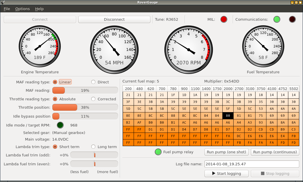
- RoverGauge is a graphical front-end that uses libcomm14cux to read data from the ECU. It displays engine temperature, road speed, engine speed, and other details, using meters and gauges.
Downloads
Both Linux and Windows packages are available to download: